JEE MAIN 2021 · 31 AUG S1Capacitors in DC circuits (steady state)TRANSCRIBED
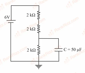
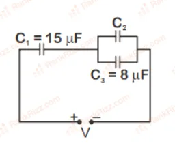
A capacitor of 50F is connected in a circuit as shown in figure. The charge on the upper plate of the capacitor is _________ C.
Every Capacitance question JEE Main has set, grouped by the idea it tests rather than the order of the syllabus. 174 questions across 7 distinct ideas. Free to read, answer key on every one.
Questions
174
Distinct ideas
7
Share of marks
2.8%
Difficulty
MEDIUM
A chapter is not one subject — it is a handful of procedures the examiner reuses. These are the ones Capacitance questions actually test.
101–120 OF 174 · NEWEST FIRST
A capacitor of 50F is connected in a circuit as shown in figure. The charge on the upper plate of the capacitor is _________ C.
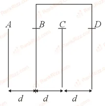
Four identical rectangular plates with length, cm and breadth, cm are arranged as shown in figure. The equivalent capacitance between and is . The value of is ________. (Round off to the Nearest Integer)
A parallel plate capacitor whose capacitance is 14 pF is charged by a battery to a potential difference V between its plates. The charging battery is now disconnected and a porcelain plate with is inserted between the plates, then the plate would oscillate back and forth between the plates with a constant mechanical energy of ________ pJ. (Assume no friction)
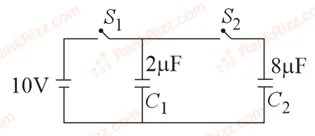
A 2F capacitor is first charged to a potential difference of 10 V using a battery. Then the battery is removed and the capacitor is connected to an uncharged capacitor of 8F. The charge in on equilibrium condition is ________ C. (Round off to the Nearest Integer)
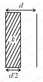
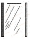
In a parallel plate capacitor set up, the plate area of capacitor is 2 m and the plates are separated by 1 m. If the space between the plates are filled with a dielectric material of thickness 0.5 m and are 2 m (see figure) the capacitance of the set-up will be ________.
(Dielectric constant of the material = 3.2) (Round off to the Nearest Integer)
In the circuit shown in the figure, the total charge is 750 and the voltage across capacitor is 20 V. Then the charge on capacitor is:
A parallel plate capacitor has plates of area A separated by distance d between them. It is filled with a dielectric which has a dielectric constant that varies as where is the distance measured from one of the plates. If , the total capacitance of the system is best given by the expression:
A 10 F capacitor is fully charged to a potential difference of 50 V. After removing the source voltage it is connected to an uncharged capacitor in parallel. Now the potential difference across them becomes 20 V. The capacitance of the second capacitor is:
15 F
30 F
20 F
10 F
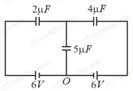
In the circuit shown, charge on the capacitor is:
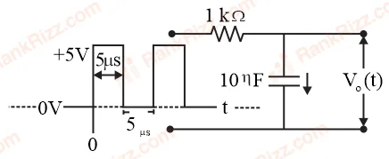
For the given input voltage waveform , the output voltage waveform , across the capacitor is correctly depicted by:
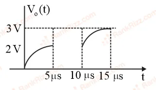
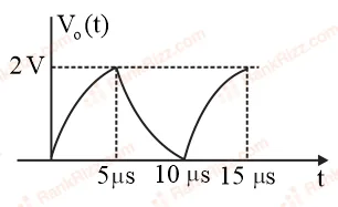
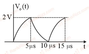
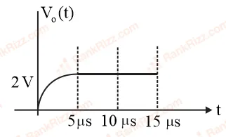
A parallel plate capacitor has plate of length , width and separation of plates is . It is connected to a battery of emf . A dielectric slab of the same thickness and of dielectric constant is being inserted between the plates of the capacitor. At what length of the slab inside plates, will the energy stored in the capacitor be two times the initial energy stored?
Effective capacitance of parallel combination of two capacitors and is 10F. When these capacitors are individually connected to a voltage source of 1V, the energy stored in the capacitor is 4 times that of . If these capacitors are connected in series, their effective capacitance will be:
4.2 F
3.2 F
1.6 F
8.4 F
A capacitor C is fully charged with voltage . After disconnecting the voltage source, it is connected in parallel with another uncharged capacitor of capacitance . The energy loss in the process after the charge is distributed between the two capacitors is:
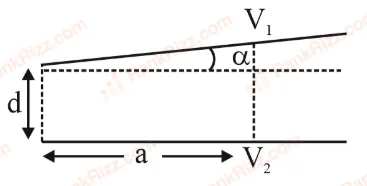
A capacitor is made of two square plates each of side 'a' making a very small angle between them, as shown in figure. The capacitance will be close to:
Two capacitors of capacitances and are charged to potential differences and , respectively. These are then connected in parallel in such a manner that the positive terminal of one is connected to the negative terminal of the other. The final energy of this configuration is:
zero
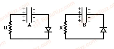
Two identical capacitors and , charged to the same potential are connected in two different circuits as shown below at time . If the charge on capacitors and at time is and respectively, then (Here is the base of natural logarithm)
A 5 F capacitor is charged fully by a 220 V supply. It is then disconnected from the supply and is connected in series to another uncharged 2.5 F capacitor. If the energy change during the charge redistribution is J then value of X to the nearest integer is:
A 60 pF capacitor is fully charged by a 20 V supply. It is then disconnected from the supply and is connected to another uncharged 60 pF capacitor in parallel. The electrostatic energy that is lost in this process by the time the charge is redistributed between them is (in nJ)
An ideal cell of emf 10V is connected in circuit shown in figure. Each resistance is . The potential difference (in V) across the capacitor when it is fully charged is ___________.
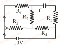
Figure shows charge (q) versus voltage (V) graph for series and parallel combination of two given capacitors. The capacitances are:
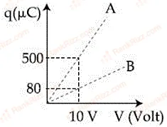
60 μF and 40 μF
50 μF and 30 μF
20 μF and 30 μF
40 μF and 10 μF
OTHER PHYSICS CHAPTERS