JEE MAIN 2021 · 18 MAR S2Series LCR circuits: impedance and phaseTRANSCRIBED
In a series LCR circuit, the inductive reactance is 10 and the capacitive reactance is 4 . The resistance in the circuit is 6 . The power factor of the circuit is :
- A
- B
- C
- D
Every Alternating Current question JEE Main has set, grouped by the idea it tests rather than the order of the syllabus. 165 questions across 7 distinct ideas. Free to read, answer key on every one.
Questions
165
Distinct ideas
7
Share of marks
2%
Difficulty
EASY
A chapter is not one subject — it is a handful of procedures the examiner reuses. These are the ones Alternating Current questions actually test.
101–120 OF 165 · NEWEST FIRST
In a series LCR circuit, the inductive reactance is 10 and the capacitive reactance is 4 . The resistance in the circuit is 6 . The power factor of the circuit is :
The angular frequency of alternating current in a L-C-R circuit is 100 rad s. The components connected are shown in the figure. Find the value of inductance of the coil and capacity of condenser.
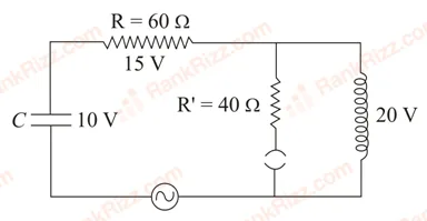
1.33 H and 150 F
0.8 H and 150 F
1.33 H and 250 F
0.8 H and 250 F
In an ac circuit, an inductor, a capacitor and a resistor are connected in series with . Impedance of this circuit is:
Zero
An AC current is given by . A hot wire ammeter will give a reading:
Match List-I with List-II.
| List - I | List - II | |
|---|---|---|
| (a) \omega L > \frac{1}{\omega C} | (i) | Current is in phase with emf |
| (b) | (ii) | Current lags behind the applied emf |
| (c) \omega L < \frac{1}{\omega C} | (iii) | Maximum current occurs |
| (d) Resonant frequency | (iv) | Current leads the emf |
(a)-(ii); (b)-(i); (c)-(iv); (d)-(iii)
(a)-(ii); (b)-(i); (c)-(iii); (d)-(iv)
(a)-(iii); (b)-(i); (c)-(iv); (d)-(ii)
(a)-(iv); (b)-(iii); (c)-(ii); (d)-(i)
Match List-I with List-II:
List-I | List-II
a. Phase difference between current and voltage in a purely resistive AC circuit | i. ; current leads voltage
b. Phase difference between current and voltage in a pure inductive AC circuit | ii. zero
c. Phase difference between current and voltage in a pure capacitive AC circuit | iii. ; current lags voltage
d. Phase difference between current and voltage in an LCR series circuit | iv.
Choose the most appropriate answer from the options given below:
(a)-(i), (b)-(iii), (c)-(iv), (d)-(ii)
(a)-(ii), (b)-(iv), (c)-(iii), (d)-(i)
(a)-(ii), (b)-(iii), (c)-(iv), (d)-(i)
(a)-(ii), (b)-(iii), (c)-(i), (d)-(iv)
In the given circuit the AC source has rad s. Considering the inductor and capacitor to be ideal, what will be the current flowing through the circuit?
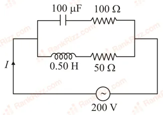
5.9 A
6 A
0.94 A
3.16 A
Find the peak current and resonant frequency of the following circuit (as shown in figure).
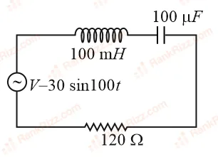
2 A and 50 Hz
0.2 A and 100 Hz
2 A and 100 Hz
0.2 A and 50 Hz
A 10 resistance is connected across 220 V - 50 Hz AC supply. The time taken by the current to change from its maximum value to the rms value is:
2.5 ms
1.5 ms
3.0 ms
4.5 ms
A 100 resistance, a 0.1F capacitor and an inductor are connected in series across a 250 V supply at variable frequency. Calculate the value of inductance of inductor at which resonance will occur. Given that the resonant frequency is 60 Hz.
0.70 H
70.3 mH
H
70.3 H
What happens to the inductive reactance and the current in a purely inductive circuit if the frequency is halved?
Both, inductive reactance and current will be halved.
Inductive reactance will be halved and current will be doubled.
Inductive reactance will be doubled and current will be halved.
Both, inducting reactance and current will be doubled
A 0.07 H inductor and a 12 resistor are connected in series to a 220 V, 50 Hz AC source. The approximate current in the circuit and the phase angle between current and source voltage are respectively. [Take as ]
8.8 A and
88 A and
0.88 A and
8.8 A and
For a series LCR circuit with , mH and pF connected across 220 V - 50 Hz AC supply, the phase angle between current and supplied voltage and the nature of the circuit is:
0, resistive circuit
90, predominantly inductive circuit
0, resonance circuit
90, predominantly capacitive circuit
Two circuits are shown in figure (a) and (b). At a frequency of _________ rad s the average power dissipated in one cycle will be the same in both the circuits.
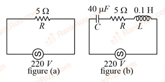
A common transistor radio set requires 12 V D.C. for its operation. The D.C. source is constructed by using a transformer and a rectifier circuit, which are operated at 220 V A.C. on standard domestic A.C. supply. The number of turns of secondary coil are 24, then the number of turns of primary are ______
A resonance circuit having inductance H and resistance 6.28 respectively oscillates at 10 MHz frequency. The value of quality factor of this resonator is ______.
A sinusoidal voltage of peak value 250 V is applied to a series LCR circuit, in which , mH and F. The value of power dissipated at resonant condition is kW. The value of to the nearest integer is ________.
A series LCR circuit of , mH and F is connected across an AC supply of 250 V, having variable frequency. The power dissipated at resonance condition is ___ W.
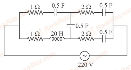
At very high frequencies, the effective impedance of the given circuit will be _________ .
An AC circuit has an inductor and a resistor of resistance in series, such that . Now, a capacitor is added in series such that . The ratio of the new power factor with the old power factor of the circuit is . The value of is _________.
OTHER PHYSICS CHAPTERS